
Flow Measurement
Compressed Air Flow Meter
A compressed air flow meter helps you see exactly where your compressed air is going and where it’s being wasted. For plants running compressors around the clock, even small leaks or inefficiencies can quietly add thousands to your energy bill every month. Accurate flow measurement lets you catch that waste early, verify the right amount of air is reaching the right point in your process, and protect both product quality and workplace safety. Instead of guessing at consumption, you get real data you can act on whether that means cutting energy costs, meeting compliance requirements, or simply keeping operations running smoothly.
For plants looking for an air flow meter for compressed air, the right measurement technology can provide reliable consumption data for monitoring system performance. WiseAir offers compressed air flow meter solutions in India for different pipe sizes, pressure conditions and installation requirements.
How do I choose the right compressed air flow meter?
With most liquid & gas flow measurement instruments, the flow rate is determined inferential by measuring the fluids velocity or the change in kinetic energy. Other factors that affect liquid flow rate include the liquid’s viscosity and density, and the friction of the liquid in contact with the pipe. With the many variations of flow meter technology available it can be challenging to make a decision on which technology is right for the application. An important and perhaps overlooked question, is what the instrument is supposed to do versus what is it able to do?
Flow meters are very popular for measuring compressed air systems. Depending on where they are installed, flow meters can tell you the compressor output, system consumption, peaks and troughs as well as average usage. When used well, flow monitoring can help keep your system under control and highlight any unusual activity in your system.
Benefits of Flow Measurement and Monitoring :
A suitable compressed air meter can help plant engineers compare actual consumption with expected demand and identify abnormal increases in air usage. This makes flow measurement useful not only for monitoring but also for day-to-day energy and maintenance decisions.
- Improves Your Compressed Air System Efficiency
- Saves Energy and Costs
- Reduces System Maintenance and Hence Lowers Labour Costs
- Reduces Operating Costs
- Keeps You Informed About Your System Dynamics
- Identifies changes in system performance
- Alerts You During Increased Leakage or Consumption.
- Tracks Your Peak and Average Demand
We Offer 3 Different Technologies in Flow Measurement for Gases and Liquids
Thermal Mass Flow Meter
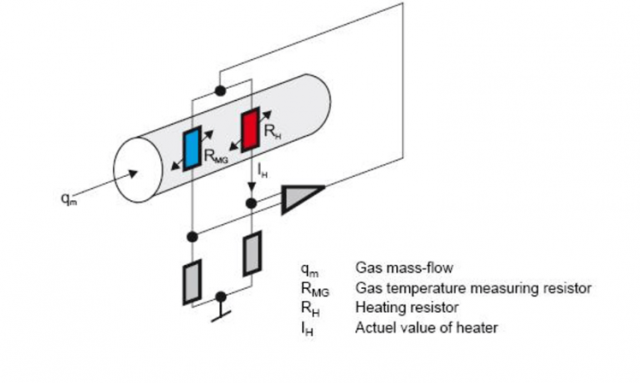
Thermal Mass Flow Meters measure the Gas Mass Flow Based on Thermal Diffusion Theory. It has two RTDs as its sensors, one of which sense the velocity of the Gas Flow (RH) and the other one will detect the temperature shift of the Gas Flow (RMG) . When the two RTD are in the Gas Flow ,the RH will be heated while the RMG will sense the temperature changing of the Gas Flow. More heat will be taken away as the velocity of the Gas Flow increases, so the temperature on RH will decline
Wise Air WAFS Series Thermal Mass Flow Meters are specially designed for Air and N2 applications. It has more compact design, which means smaller enclosure and thinner insertion tube probe. Due to its small diameter insertion probe and shorter high-sensitive sensor, it can be used on pipes from DN25~DN500, or even larger pipe.
In some higher pressure applications, it can be installed / removed without stopping the fluid, as the pipe is thinner, field engineers will be able to insert the meter to pipe very easily. Also, to full-fill the Energy Conservation Need in Compressed Air and N2 applications, WAFS Series Thermal Mass Flow Meters will be the most Cost Effective model in the market.
For applications requiring a digital air flow meter, the WAFS Series can be considered where digital flow monitoring and reliable compressed-air measurement are required. The suitable model depends on the pipe size, operating conditions and required measurement range.

What pipe size and installation options are available?
The WAFS Series Thermal Flow Meters have two different installation types, one is insertion and the other is in-line type.
The insertion type can be installed and maintained on line. To install it, you have to weld and install a socket with screw thread outside on the pipe and install a 1 inch or 1/2 inch ball valve on the base. Then drill a hole of 13mm (or 22mm) diameter on the pipe with a special tool and install the Flow meter on the pipe through the hole. The position and depth of how the sensor is fixed have already been set before delivery.
The fitting in diameter of pipe for insertion type: DN25~ 900mm (Please make sure to let us know if you need it for larger diameter)
The In-line type is delivered along with a pipe which has a same inner diameter as the pipe in field. Is should be installed through flange or screw thread. The flanges meet GB/T9119-2000 standard(or ANSI B16.5 or DIN or JIS standard. The in-line type can fit in pipe with diameter from DN15mm to DN300mm. Or customer can simply choose to use a 3-way pipe to replace the flanged body
Sensor is made in 316 stainless steel and the pipe is made in 304 or 316 stainless steel. If users need them to be made in different material, please let us know before confirming the order.
Special Design
Anti Ejection Design
In some High Pressure Applications, there is a risk that when the pressure is too high, the nut sleeve will fail or be loosened unintentionally and the Flow meter will be ejected out and cause damage or injury.
In Our WAFS Series insertion Thermal Mass Flow Meter the sensor base is wider than the nut sleeve and hence as long as the sleeve is still fixed on pipe with thread, the meter will not be totally ejected out even when used in High Pressure Applications.
Ball Valve Mounting
When users want to replace or re-calibrate or for any reason want to remove the Flow meter without stopping the Flow in the pipeline, our ball valve mounting can help. Once the meter is installed with a customized ball valve, user can remove the meter away while still keeping the pipeline sealed with the ball valve.
This design should only be used when it is absolute necessary and the fluid is not explosive or hazard.
Online Drilling
Some user may not want to stop the Flow when installing the Flow meter. With the help of our Online Drilling Kit the required provision can be made without plant shutdown.
The Online Drilling Kit can help you drill a hole for inserting the Flow meter without stopping the Flow. It will work with a ball valve. And after drilling and removing the tool , the pipe will be totally sealed.
Differential Pressure Pitot Tube Flow Meter
Differential pressure Pitot tube Flow Meters use Bernoulli’s equation to measure the flow of fluid in a pipe. Differential pressure pitot tube Flow Meters introduce a constriction in the pipe that creates a pressure drop across the Flow Meter. When the flow increases, more pressure drop is created. Impulse piping routes the upstream and downstream pressures of the Flow Meter to the transmitter that measures the differential pressure to determine the fluid flow.
Differential Pressure Pitot tube flow meters are ideally suited to wet, dirty and high velocity gases. The extremely sensitive differential pressure measurement allows this sensor to be used over a wide flow range. The patented anti condensation technology enables the sensor to be used under saturated conditions and ensures the sensor will perform stable accurate measurements for years to come .Pitot tube flow sensor measure the upstream dynamic pressure and downstream static pressure.
The pressure differential is a measure of the velocity and flow rate.online auto-calibration technology, high reliability, long-term measurement and accuracy can be guaranteed .Pitot flow meters are widely used in industrial processes, chemical, petrochemical, power engineering, etc.Pitot Tube flow meters are ideal for both temporary or permanent installations.

Ultra Sonic Flow Meter
Ultrasonic Flow Meters use sound waves to determine the velocity of a fluid flowing in a pipe. At no flow conditions, the frequencies of an ultrasonic wave transmitted into a pipe and its reflections from the fluid are the same.
Under flowing conditions, the frequency of the reflected wave is different due to the Doppler effect. When the fluid moves faster, the frequency shift increases linearly. The transmitter processes signals from the transmitted wave and its reflections to determine the flow rate.
Transit time ultrasonic Flow Meters send and receive ultrasonic waves between transducers in both the upstream and downstream directions in the pipe. At no flow conditions, it takes the same time to travel upstream and downstream between the transducers. Under flowing conditions, the upstream wave will travel slower and take more time than the (faster) downstream wave. When the fluid moves faster, the difference between the upstream and downstream times increases. The transmitter processes upstream and downstream times to determine the flow rate.
Where pipeline modification or shutdown is difficult, a clamp on ultrasonic flow meter for compressed air can be considered for non-invasive flow measurement. The suitability depends on pipe material, pipe size, pressure and installation conditions.

Which model is right for your system?
Selection depends on pipe size, pressure, flow range and how the data needs to reach you. Tell us your application and we will shortlist the models that fit and send the datasheets.
Prefer to talk? Call +91 90477 78715 or +91 98944 49015. Working out whether it pays? Try the savings and ROI calculator or the leak cost calculator.
WISEAIR TECHNOLOGIES INDIA LLP
# 12 Sri Venkatalakshmi Nagar, Singanallur,
Coimbatore – 641005 India.

WiseAir Technologies India LLP is part of the Systel Asia group — specialists in compressed air management and smart monitoring solutions across Asia since 2002.
© Copyright 2026. WiseAir Technologies India LLP
Which model is right for your system?
Selection depends on pipe size, pressure, flow range and how the data needs to reach you. Tell us your application and we will shortlist the models that fit and send the datasheets.
Prefer to talk? Call +91 90477 78715 or +91 98944 49015. Working out whether it pays? Try the savings and ROI calculator or the leak cost calculator.